User Manual Download Link:
https://www.dropbox.com/scl/fo/pxbzb1s6q0b47s55ttnln/ABYqGPmjXHPgBLbr-lLHKEw?rlkey=wggbrnn0jw540unqcuw6iharm&st=0y056jks&dl=0Tool List:
- 17mm Socket
- T25 Torx Bit
- Trim Removal Tools
- Airbag removal tool
- Socket Set
- Phillips screwdriver
- Torque Wrench
*(Please download the User Manual above for the product list needed for this installation)
Step 1: Ensure both the steering wheel and wheels are completely straight and disconnect the battery

CAUTION: Disconnect the battery negative lead using a 10mm socket before proceeding with the installation!
Step 2: Insert the airbag removal tool directly into the concealed opening located in the backside of the steering wheel until you feel the spring resistance.


Repeat this process on the opposite side and the lower side of the steering wheel.

Disconnect and detach the airbag, horn and information connection plugs, then remove the airbag carefully.


Afterward, proceed to unbolt the steering wheel center bolt using a 17mm socket to take off the factory steering wheel. It’s crucial to maintain the clock spring ring in its original position without spinning to prevent any damage from occurring due to excessive turning.

(If you damage the clockspring during this step, you will lose all steering wheel functions after installation. Then you need to replace the entire clockspring)
CAUTION: Risk of injury. Handle the airbag unit carefully, ensuring that the battery is always disconnected and the airbag is always facing upwards when it is being set down!
Step 3: Use a phillips screwdriver to loosen the screens of both sides of the steering wheel column cover


Step 4: Use a trim removal tool to unclip the steering column and remove the upper and lower cover

Step 5 : Locate the factory white male plug in the below pictures and carefully unplug it. Then connect the factory white male plug to the female plug of the Madtrace Main Harness Adapter (#9 on the Product List). Then plug the white male plug of the Madtrace Main Harness Adapter into the factory female plug.


CAUTION: The Madtrace Main Harness Adapter is only compatible with the Madtrace Racing Steering Wheel System, designed for off-road, track use, racing, and competition purposes!
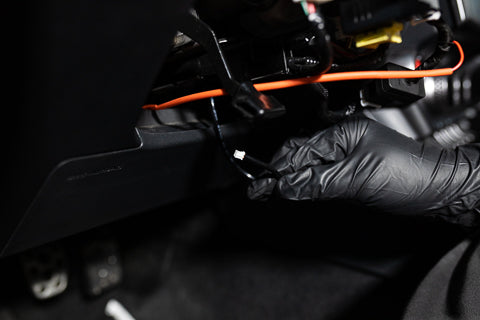
Insert the Fuse Connector end of the Madtrace Main Harness Adapter (#9 on the Product List) through the steering column and route it down to the left side of the driver side footwell.


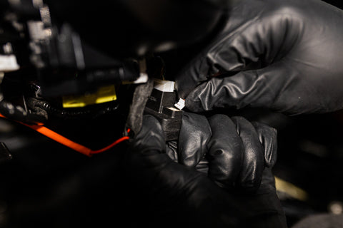
Above the left side of the driver side footwell, insert the fuse connector of the Madtrace Main Harness adapter (#9 on the Product List) into the fuse box (10A ECU ACC Fuse)


CAUTION: The Madtrace Main Harness Adapter is only compatible with the Madtrace Racing Steering Wheel System, designed for off-road, track use, racing, and competition purposes!
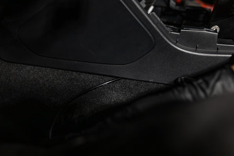
Step 6: Locate the cover for the center console bolts on both bottom sides of the center console cup holder. Pop off the cover with a trim removal tool and use a phillips screwdriver to remove the screws. (Two screws (Driver & Passenger side))


Use a trim removal tool to carefully remove and unclip the center console trim (Screw Driver as demostration, please use trim removal tool to prevent damage of the trim piece)

After you remove the trim, it will reveal two bolts that are used to secure the center console. Remove the two bolts (One of each side)

Use a trim removal tool to carefully remove and lift the E-Brake cover off.


Once you lift the e-Brake Cover, use a phillips screwdriver to remove the two center console screws (Driver/Passenger side)

Once you removed the screws, use a trim removal tool to carefully remove and lift the center console trim (Silver trim around the shifter)

Use a Phillips screwdriver to remove the last two remaining screws above the ESP Buttons.

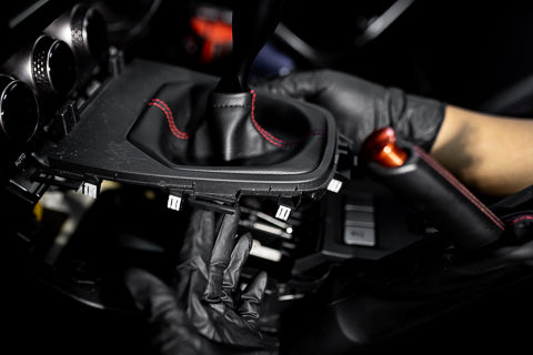
Use a trim removal tool to carefully unclip and lift up the shifter boot trim

Use a trim removal tool to carefully unclip and lift up the center console (Cupholder & ESP Control Unit)


Step 7: Disconnect the factory ESP function plug positioned at the back of the center console trim. Then, connect the Madtrace ESP Drive Mode Harness Adapter (#10 on the Product List) with the factory ESP plug and the factory ESP harness.


Step 8: Connect one end of the Connection Harness (#11 on the Product List) to the Track Mode/ESP Harness Adapter (#10 on the Product List) behind the left lower plastic panel, then connect the other end of the Connection Harness (#11 on the Product List) to the Madtrace Main Harness Adapter plug (#9 on the Product List) underneath the steering column to activate the ESP and Track Mode function on the steering wheel.


CAUTION: Ensure a tidy and secured route for all the connection harnesses!
Step 9: Install the Madtrace Airbag Resistors (#7 on the Product List) onto the airbag harness, then carefully wrap the resistors with electrical tape to prevent them from falling off or having poor contact. After that,reinstall all the removed trims or plastic pieces back into their positions.


CAUTION: The Madtrace Airbag Resistors are only compatible with the Madtrace Racing Steering Wheel System, designed for off-road, track use, racing, and competition purposes!
Step 10: Insert the two yellow airbag harnesses through the back side of the adapter hub and insert the quick-release harness through the front side of the hub


Plug the harness from the quick-release harness

If you have the version shown below, make sure to connect the two black ground wires.

Mount the adapter hub onto the steering column and attach the quick-release onto the adapter hub. Next, use the provided Madtrace locking wrench to secure the adapter hub in place with two M5x14mm bolts to hold it firmly. Then tighten the steering wheel center bolts with a torque wrench set to 30 ft/lb(41 NM) to securely fasten the adapter hub.


CAUTION: Apply a torque of 30 ft/lb(41NM) to the steering center bolt!
Step 11: Ensure that both the adapter hub and quick release base are aligned straight with the steering column. Proceed to secure the quick release base using six provided M5x14mm bolts. Tighten the bolts firmly to establish a secure and stable connection.


Step 12: Put the steering column covers back in place

Step 13: Position and align the steering wheel onto the control hub. Proceed to insert and tighten six provided M5x35mm bolts to secure it in place.

CAUTION: Before reconnecting the battery negative lead, make sure to double-check that all components have been properly tightened up. Ensuring secure connections is essential for safe operation.
CAUTION: When the vehicle restarts after power loss from the disconnected battery, you may notice some fault codes. However, after driving the vehicle normally for a few minutes and fully restarting the vehicle , the fault codes will clear automatically.


